Export to Modelica and execution of the SysML/SysPhS block ConnectedTanks Gallery Tutorial TRAIL: SysPhS-1.1 Annex A examples in MagicDraw/Cameo SysML vs Modelica (Wolfram SystemsModeler) Section Annex A.4: Hydraulics Slide kind plot
In nonideal fluid dynamics, the Hagen–Poiseuille equation ... is a physical law that gives the pressure drop in an incompressible and Newtonian fluid in laminar flow flowing through a long cylindrical pipe of constant cross section. Source Wikipedia
SysPhS-1.1: p.81: 'resistance:ViscousResistance' (in Figure 60) has to be treated as a PhSVariable not a PhSConstant, otherwise get an invalid system with 6 variables and 7 equations.
Parametric diagrams: Figure 62, Figure 63 Gallery Tutorial TRAIL: SysPhS-1.1 Annex A examples in MagicDraw/Cameo SysML vs Modelica (Wolfram SystemsModeler) Section Annex A.4: Hydraulics Slide kind hybrid diagram SysML Parametric Diagram
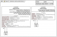
Also, the fluid flow in the tank, fluidFlow, is related to the change in the fluid height level fluidHeight over time and the cross-sectional surface area of the tank, surfaceArea. Source SysPhS-1.1
The tank constraints specify that the pressure in the tank, pressure depends on the height of the fluid level in the tank, fluidHeight, as well as properties of the fluid, fluidDensity. Source SysPhS-1.1
The sum of the fluid flow rates going through the two pipe openings is zero (the fluid is assumed to be incompressible). Source SysPhS-1.1
The magnitude of fluid flow rate through the pipe fluidFlow is the same as the magnitude of flow rates opening1FluidFlow and opening2FluidFlow going through the pipe’s openings, though the values differ in sign. Source SysPhS-1.1
The fluid flow rate through the pipe, fluidFlow, is proportional to the pressure difference by the constant resistance, which depends on the geometric properties of the pipe as well as fluidic properties. Source SysPhS-1.1
The pipe constraints specify that the pressure pressureDiff across it is equal to the difference of fluid pressures opening1Pressure and opening2Pressure at each end of the pipe. Source SysPhS-1.1
BDD: Figure 61: Hydraulics model constraint blocks Gallery Tutorial TRAIL: SysPhS-1.1 Annex A examples in MagicDraw/Cameo SysML vs Modelica (Wolfram SystemsModeler) Section Annex A.4: Hydraulics Slide kind SysML Block Definition Diagram (BDD)
SysML initial values specify property values for components used in internal block diagrams. Figure 59 shows initial values for fluid density, gravity, tank surface area, pipe radius, pipe length, and dynamic viscosity of the fluid ... Source SysPhS-1.1
Item flows on connectors indicate fluid passes through the ports and between the parts. The diagram connects a tank to each end of a pipe. Source SysPhS-1.1
Part properties, typed by blocks ... represent components in this system. They are connected to each other through ports, which represent openings in the tanks and pipe ... Source SysPhS-1.1
Tanks and pipes have openings for fluid to pass through, one for tanks and two for pipes. The openings are represented by ports of type VolumeFlowElement, from the physical interaction library .. Source SysPhS-1.1
A.4.1 Introduction: This subannex gives a model of a simple hydraulic system as an example of physical interaction (fluid flow). It does not include any signal flows Source SysPhS-1.1
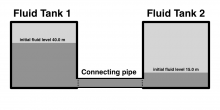
A.4.2 System being modeled: The hydraulic system has three components: two fluid reservoir tanks and a pipe for connecting these tanks, see Figure 58. Source SysPhS-1.1
Figure 58: Hydraulics example (MOCKUP) Gallery Tutorial TRAIL: SysPhS-1.1 Annex A examples in MagicDraw/Cameo SysML vs Modelica (Wolfram SystemsModeler) Section Annex A.4: Hydraulics Slide kind drawing